Table of Contents
Automatic Pneumatic Bumper For Two Wheeler | Mechanical Project with Report pdf
This Project require basic knowledge ofPneumatic systemandMechatronics.
SYNOPSIS
The
technology of pneumatic has gained tremendous importance in the field of
workplace rationalization and automation from old-fashioned timber works and
coal mines to modern machine shops and space robots. It is therefore important
that technicians and engineers should have a good knowledge of pneumatic
system, air operated valves and accessories.
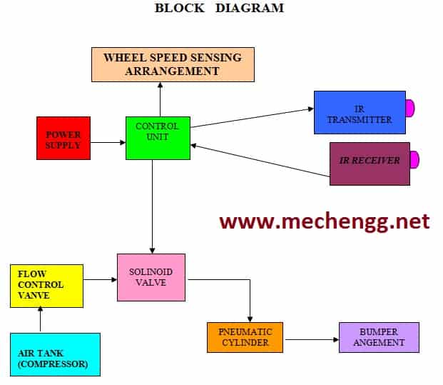
The aim is to design and develop a control system based an intelligent
electronically controlled automotive bumper activation system is called “AUTOMATIC PNEUMATIC BUMPER”. This system is consists of IR transmitter and Receiver circuit, Control Unit,
Pneumatic bumper system. The IR sensor is used to detect the obstacle. There is
any obstacle closer to the vehicle (with in 4 feet), the control signal is
given to the bumper activation system.
The
pneumatic bumper system is used to product the man and vehicle. This bumper
activation system is only activated the vehicle speed above 40-50 km per hour.
This vehicle speed is sensed by the proximity sensor and this signal is given
to the control unit and pneumatic bumper activation system.
See Also: Automatic Pneumatic Bumper
Introduction
We have pleasure in introducing our new project“AUTOMATIC PNEUMATIC BUMPER”, which is fully equipped byIR sensors circuitandPneumatic bumper activation circuit. It is a genuine project which is fully equipped and designed for Automobile vehicles. This forms an integral part of best quality. This product underwent strenuous test in our Automobile vehicles and it is good.
Components Required :
1)
PNEUMATIC SINGLE ACTING CYLINDER
2)
SOLENOID VALVE
3)
FLOW CONTROL VALVE
4)
IR SENSOR UNIT
5)
WHEEL AND BRAKE ARRANGEMENT
6)
PU CONNECTOR, REDUCER, HOSE COLLAR
7)
STAND
8)
SINGLE PHASE INDUCTION MOTOR.
Working:
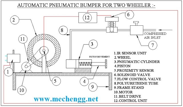
If the solenoid valve is activated, the compressed air passes to the Single Acting Pneumatic Cylinder. The compressed air activate the pneumatic cylinder and moves the piston rod
If the
piston moves forward, then the breaking arrangement activated. The breaking
arrangement is used to break the wheel gradually or suddenly due to the piston movement. The breaking speed is varied by adjesting the valve is called“FLOW CONTROL VALVE”
In our
project, we have to apply this breaking arrangement in one wheel as a model.
The compressed air drawn from the compressor in our project. The compressed air
flow through the Polyurethane tube to the flow control valve. The flow control
valve is connected to the solenoid valve as mentioned in the block diagram.
Download:
Automatic Pneumatic Bumper For Two Wheeler | Mechanical Project with Report pdf
More Resources /articles
Best Low Cost Mechanical Projects
Drilling Machine Projects
Material Handling Projects
New Mechanical Projects 2020 ( All Projects Post Index List )
Related posts:
 Project On Automatic Pneumatic Bumber Mechanical Project
 Intelligent Braking System in Four Wheeler – Mechanical Project
 Automatic Pneumatic Clutch and Braking System
 Two wheeler Related Automobile Mechanical Engineering Projects
 AUTOMATIC GEAR CHANGER IN TWO AND FOUR WHEELER VEHICLE
 Automatic Pneumatic Sand Ramming Machine Mechanical Project
 Automatic Pneumatic Water Pumping System Mechanical Project
 AUTOMATIC PNEUMATIC GRINDING MACHINE | MECHANICAL PROJECT