测功器钻设计和制造的工具-Mechanical Project
Introduction:
Dynamometers are devices used to measure cutting forces in machining operation. The cutting force cannot be detected or quantified directly but their effect can be sensed using Transducer. For example, a force which can neither be seen nor be gripped but can be detected and also quantified respectively by its effect and the amount of those effects (on some material) like elastic deflection, deformation, pressure, strain etc.nThese effects, called signals, often need proper conditioning for easy, accurate and reliable detection and measurement. In other words,
Measurement involves three stages
- Conversion into another suitable variable (deflection, expansion etc)
- Amplification, filtration and stabilization
- Reading or recording
Measurement of cutting force(s) is based on three basic principles:
- measurement of elastic deflection of a body subjected to the cutting force
- measurement of elastic deformation, i.e. strain induced by the force
- 测量的压力中等发达的the force.
Requirement of a cutting force dynamometer
- The dynamometer should have sufficient mechanical rigidity to avoid excessive deformation of the cutting edge under the action of cutting forces
- It should have sufficient sensitivity to enable measurement of cutting forces with sufficient accuracy
- It should have high stiffness and low mass, ensuring 100 percent transmissibility of force by its very high natural frequency. This feature will also enable the recorded force to be unaffected by the exciting vibration due to machining process itself. Example : milling , grinding and shaping
- It should be capable of indicating individual force components without any cross effect, while measuring such forces simultaneously
- The measuring system should be stable with reference to time, temperature and humidity, requiring only occasional checking after calibration.
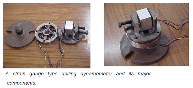
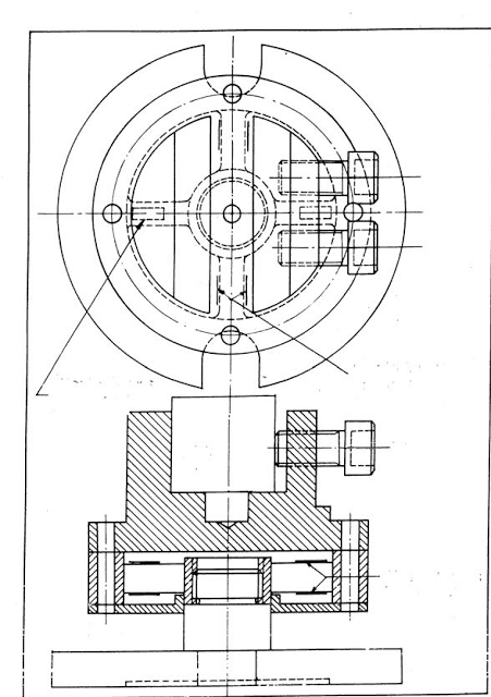
Drilling dynamometer
Physical construction of a strain gauge type 2 – D drilling dynamometer for measuring torque and thrust force is typically shown schematically in Fig.and pictorially in Fig.. Four strain gauges are mounted on the upper and lower surfaces of the two opposite ribs for PX – channel and four on the side surfaces of the other two ribs for the torque channel. Before use, the dynamometer must be calibrated to enable determination of the actual values of T and PX from the voltage values or reading taken in SMB or PC.
Increasing deflection, δ enhances sensitivity of the dynamometer but may affect machining accuracy where large value of δ is restricted, the cutting forces are suitably measured by using the change in strain caused by the force.
The strain, ε induced by the force changes the electrical resistance, R, of the strain gauges which are firmly pasted on the surface of the tool-holding beam as
Gauge Factor = (Change in resistance /original resistance )
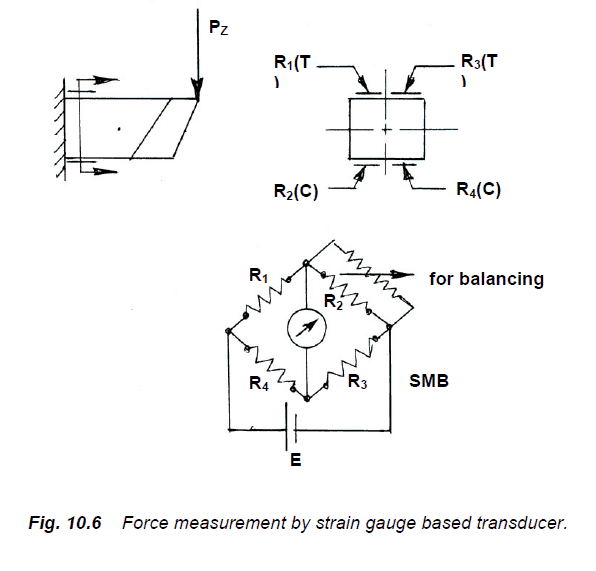
The gauge connections may be
• full bridge (all 4 gauges alive) – giving full sensitivity
• half bridge (only 2 gauges alive) – half sensitive
• quarter bridge (only 1 gauge alive) –1/4 th sensitivity
Related posts:
 Dynamometer | Types Of Dynamometer used For Torque measurement
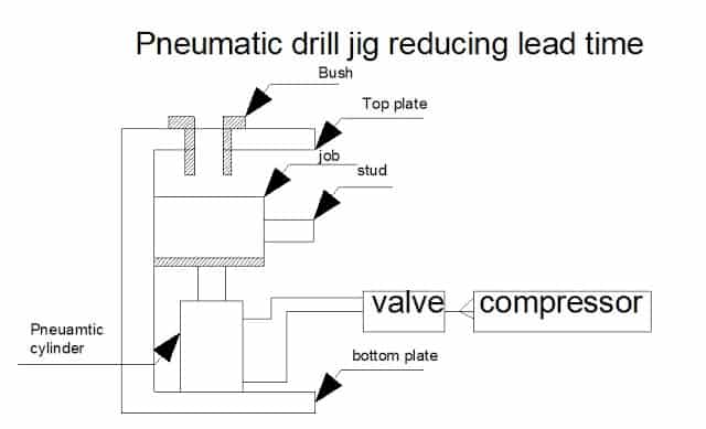 DESIGN AND FABRICATION OF PNEUMATIC DRILL JIG FOR REDUCING LEAD TIME
 Factor Affecting on Tool Life- taylor’s Equation For tool Life Calculation
 FABRICATION OF HELICAL SPRING LOAD TESTING MACHINE
 Design a drill jig for drilling on cylindrical surface – Mechanical Project
 Design and Fabrication Of A Blanking Tool Report Download Projects
 DESIGN AND FABRICATION OF SPHERICAL TURNING TOOL FOR LATHE MACHINE