Table of Contents
Seminar On Space Robotics -Report Free Download
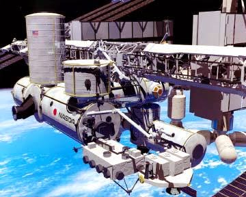
Introduction to space Robotics :
Robot is a system with mechanical body, using computer as its brain. Integrating the sensors and actuators built into the mechanical body, the motions are realised with the computer software to execute the desired task. Robots are more flexible in terms of ability to perform new tasks or to carry out complex sequence of motion than other categories of
automated manufacturing equipment. Today there is lot of interest in this field and a separate branch of technology ‘robotics’ has emerged. It is concerned with all problems of robot design, development and applications. The technology to substitute or subsidise the manned activities in space is called space robotics. Various applications of space robots are the inspection of a defective satellite, its repair, or the construction of a space station and supply goods to this station and its retrieval etc. With the over lap of knowledge of kinematics, dynamics and control and progress in fundamental technologies it is about to become possible to design and develop the advanced robotics systems. And this will throw open the doors to explore and experience the universe and bring countless changes for the better in the ways we live.
automated manufacturing equipment. Today there is lot of interest in this field and a separate branch of technology ‘robotics’ has emerged. It is concerned with all problems of robot design, development and applications. The technology to substitute or subsidise the manned activities in space is called space robotics. Various applications of space robots are the inspection of a defective satellite, its repair, or the construction of a space station and supply goods to this station and its retrieval etc. With the over lap of knowledge of kinematics, dynamics and control and progress in fundamental technologies it is about to become possible to design and develop the advanced robotics systems. And this will throw open the doors to explore and experience the universe and bring countless changes for the better in the ways we live.
STRUCTURE OF SPACE ROBOTS
DESCRIPTION OF STRUCTURE OF SPACE ROBOT
The proposed robot is of articulated type with 6 degrees of freedom (DOF). The reason for 6 DOF system rather than one with lesser number of DOF is that it is not possible to freeze all the information about possible operations of the payload/racks in 3D space to exclude some DOF of the robot. Hence, a versatile robot is preferred, as this will not impose any constraints on the design of the laboratory payload/racks and provide flexibility in the operation of the robot. A system with more than six DOF can be provided redundancies and can be used to overcome obstacles. However, the complexities in analysis and control for this configuration become multifold.
机器人由两个武器即一个上臂nd a lower arm. The upper arm is fixed to the base and has rotational DOF about pitch and yaw axis. The lower arm is connected to the upper arm by a rotary joint about the pitch axis. These 3 DOF enable positioning of the end effector at any required point in the work space. A three-roll wrist mechanism at the end of the lower arm is used to orient the end effector about any axis. An end effector connected to the wrist performs the required functions of the hand. Motors through a drive circuit drive the joint of the arm and wrist. Angular encoders at each joint control the motion about each axis. The end effector is driven by a motor and a pressure sensor/strain gauges on the fingers are used to control the grasping force on the job.
DESCRIPTION OF SUBSYSTEMS
The main subsystems in the development of the manipulator arm are
-
Joints
-
Arm
-
Wrist
-
Gripper
JOINTS
A joint permits relative motion between two links of a robot.
Two types of joints are
-
Roll joint –rotational axis is identical with the axis of the fully extended arm.
-
Pitchjoint– rotational axis is perpendicular to the axis of the extended arm
and hence rotation angle is limited.
The main requirements for the joints are to have near zero backlash, high stiffness and low friction. In view of the limitations on the volume to be occupied by the arm within the workspace, the joints are to be highly compact and hence they are integrated to the arm structure. To ensure a high stiffness of the joint the actuator, reduction gear unit and angular encoders are integrated into the joint.
Each joint consists of
-
Pancake type DC torque motors (rare earth magnet type) which have advantage over other types of motors with respect to size, weight, response time and high torque to inertia ratio.
-
Harmonic gear drive used for torque amplification/speed reduction. These gear drives have near zero backlash, can obtain high gear ratios in one stage only and have high efficiency.
-
Electromagnetically actuated friction brakes, which prevent unintentional movements to the arms. This is specifically required when the gear drive is not self-locking. In space environment, where the gravity loads are absent (zero ‘g’ environment) brakes will help to improve the stability of the joint actuator control system. i.e. the brake can be applied as soon as the joint velocity is less than the threshold value.
-
Electro optical angular encoders at each axis to sense the position of the end of the arm. Space qualified lubricants like molybdenum disulphide (bonded film/sputtered), lead, gold etc. will be used for the gear drives and for the ball bearings.
ROBOT ARMS
The simplest arm is the pick and place type. These may be used to assemble parts or fit them into clamp or fixture. This is possible due to high accuracy attainable in robot arm. It is possible to hold the part securely after picking up
and in such a way that the position and the orientation remains accurately known with respect to the arm. Robot arms can manipulate objects having complicated shapes and fragile in nature.
and in such a way that the position and the orientation remains accurately known with respect to the arm. Robot arms can manipulate objects having complicated shapes and fragile in nature.
WRIST
Robot arm comprises of grippers and wrist. Wrist is attached to the robot arm and has three DOF (pitch, yaw, and roll). Wrist possesses the ability to deform in response to the forces and the torques and return to equilibrium
position after the deflecting forces are removed.
position after the deflecting forces are removed.
GRIPPER
Gripper is attached to the wrist of the manipulator to accomplish the desired task. Its design depends on the shape and size of the part to be held.
CONCLUSION
In the future, robotics will make it possible for billions of people to have lives of leisure instead of the current preoccupation with material needs. There are hundreds of millions who are now fascinated by space but do not have the means to explore it. For them space robotics will throw open the door to explore and experience the universe.
Download :Seminar On Space Robotics -Report Free Download
Latest seminar topic index - Report ,PPT Download
Product Ideas , Innovative Machine Ideas Projects
Non traditional machining Projects
Related posts:
 Seminar on Agricultural Robots Report Pdf Free Download
 (31+) Latest Seminar Topics For Mechanical Engineers | Seminar report pdf-ppt Download
 Seminar On Free Piston Engine report Download | Mechanical Seminar
 Seminar on Shaping Machine pdf Report Free Download
 Robotics and Automation Online Notes , Objective and Interview Questions
 Seminar On Rotary Engine Report Pdf Free Download
 Seminar on Ocean energy Report free Pdf Download
 Seminar On 3D Printing Technology Report pdf Free Download